Skip to content

Software

Software makes sure we can control, communicate, automate, and see the rover. We utilize the full potential of our hardware with tuned control loops, thorough testing, and streamlined communication between each subsystem. Our expertise includes blowing up motors, and kindly asking the mechanical teams for unscheduled maintenance.

The systems we build

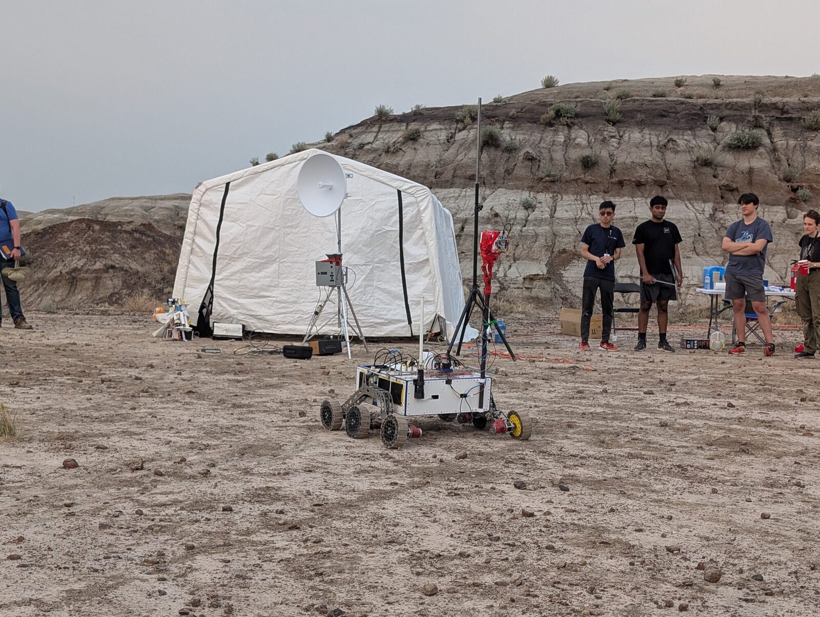
The dish at competition, tracking the rover downrange.

Communications & Perception

This critical subsystem allows the operator to control and see our rover in real time.

Our communications system is a 5 GHz point-to-point network, optimized for range and throughput. Using H.265 compression, we can stream multiple camera feeds at the same time over our network.

Many teams use two omnidirectional antennas, however we use a dish to manually or automatically rotate towards the rover. This allows us to communicate with our rover at large distances with a high throughput.

Our network has an effective range of 780 m with an average latency of under 3 ms. It can also stream up to 5 camera feeds at 30 fps simultaneously.

Tech Specs

Bandwidth
20–80 MHz
Antennas
2 omnidirectional, 5 GHz powerbeam
Range
780 m
Latency
Under 3 ms
Camera feeds
5
Compression
H.265

Photo slot

SOFTWARE-02

Autonomy on the UBC Rover.

  • Software RL.mp4 - video

Autonomy

Enables the rover to navigate, perceive, and manipulate its environment without direct human control.

The Autonomy subsystem gives the rover the ability to independently traverse unknown terrain and perform manipulation tasks with the robotic arm. It combines Visual SLAM (VSLAM) for localization and path planning with computer vision for object and marker detection, allowing the rover to complete GNSS-only navigation, AR tag post-finding, and object-retrieval missions autonomously.

We chose a VSLAM based approach over relying solely on GNSS because GPS accuracy alone isn't sufficient for precise final-approach navigation to posts and objects, especially in terrain with signal degradation. VSLAM lets the rover build a local map in real time and correct its position using visual features. For the arm, our only supported autonomy stack involves RL - which is still in development. Using behavior trees and excluding an observation module, we trained a hierarchical reinforcement learning model to dynamically press keys on a keyboard in simulation. Overall, we prioritized modularity between the navigation stack and the manipulation stack so each can be tested and tuned independently before integration.

The subsystem has to operate over unstructured, uneven outdoor Mars-like terrain without reliable GPS lock at every point along the course, using onboard cameras as the primary sensing source. It must reliably detect AR tags, and small ground objects under variable outdoor lighting. The arm's vision-guided keypress task demands sub-centimeter positioning accuracy despite vibration and imperfect stopping position from the drive system.

Tech Specs

Task completion accuracy
98.7%
Method
RL with domain randomisation, excluding observation module
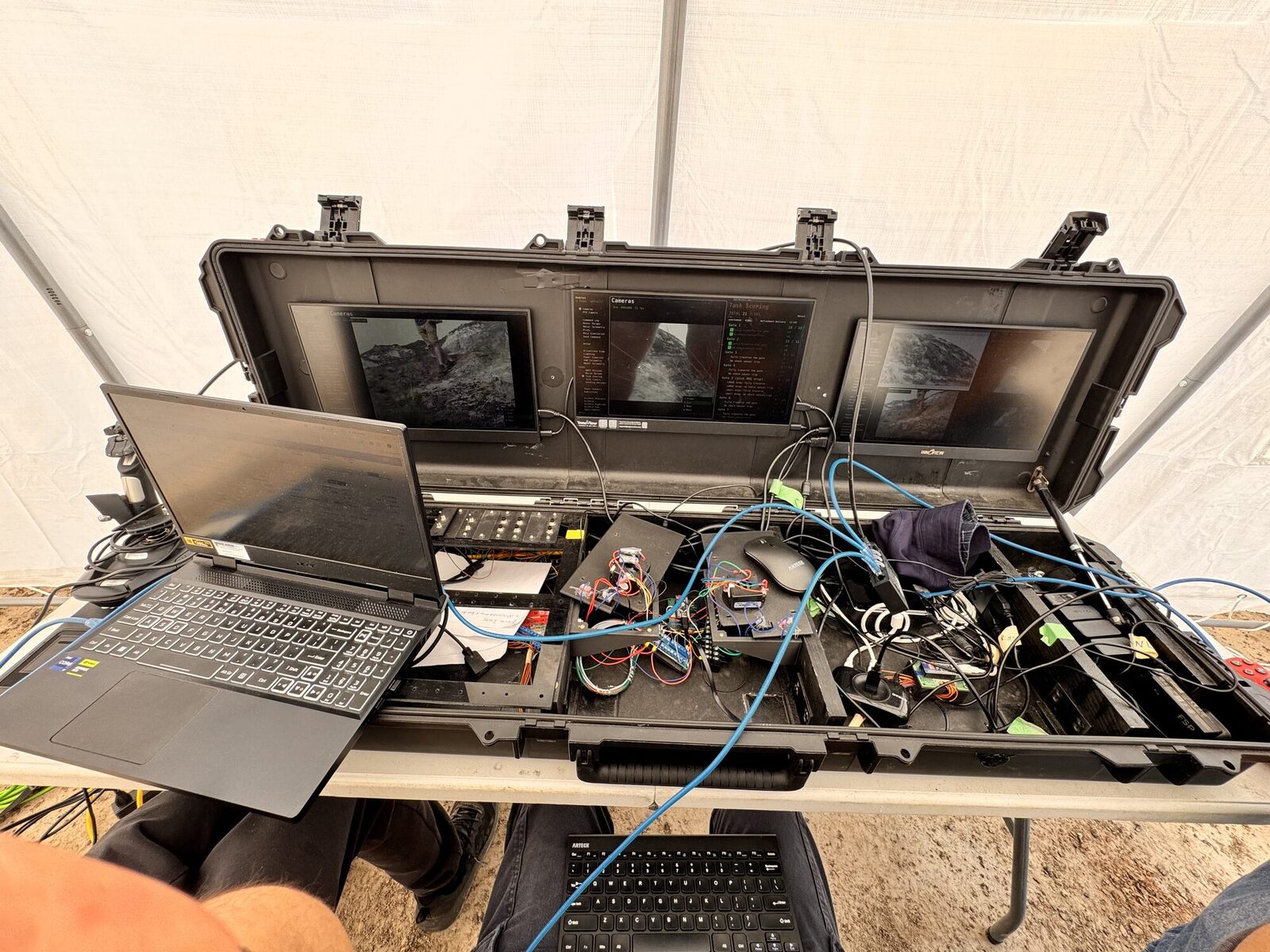
The control base set up in the field.

Control Base

The control base serves to control the rover and all its subsystems in one place during the competition.

This system has two parts. The human-machine interface (HMI) is a high-level layer that provides an intuitive visualization of the rover. Beneath it, the control stack is a low-level layer that translates joystick movements and button presses on the control base into the signals that operate the rover itself.

One important feature on our control base is having cleanly split roles. The HMI serves only as the frontend of the control base and we use many ROS nodes to provide a trustworthy backend for this system. This also allows for a modular codebase which is integral for collaboration across multiple projects and the addition of new features depending on what the other subteams require.

This subsystem operates under highly illuminated spaces. For efficient operator control, our monitors require especially high nits so that even in the brightest conditions, the operator can see everything happening easily. Our existing setup has 3 monitors, however we are considering adding additional monitors to have more room for telemetry and operation panels.

Tech Specs

Startup time
1.5 minutes
Configurable physical controls
34
Total screen space
550 cm²
Monitors
3
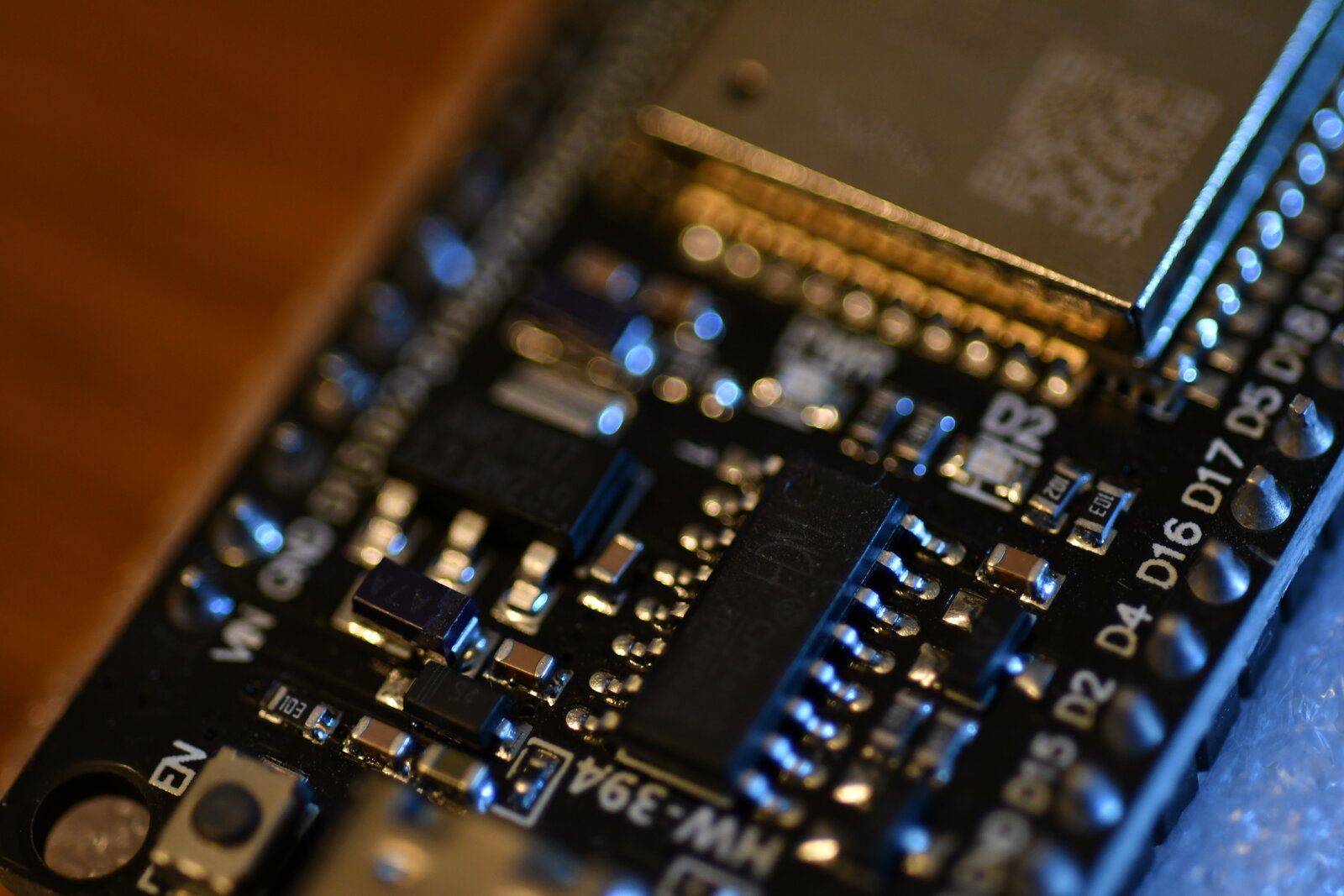
An ESP32 dev board on the bench.

Firmware & Embedded Systems

Firmware is the glue connecting our software to our sensors and actuators.

While our on-board computers handle more general tasks, our firmware is built for specific applications. It is the final layer of code that will translate a raw voltage into a temperature reading, or a software command into motor movement.

Firmware is a joint team between electrical and software. Our firmware protects our hardware by setting hard limits, while pushing our hardware to its full capabilities. We make sure the software side can utilize all our hardware's features through standardized, simple interfaces.

Our firmware operates across distributed boards exposed to vibration, EMI, and unreliable links back to the main computer. It must detect faults and recover on its own, with zero tolerance for corrupting sensor/actuator state mid-operation.

Tech Specs

Boards running custom firmware
8
Favourite controller
STM32G474
Favourite protocol
CAN FD, with SIC transceivers