Skip to content

Chassis

The Chassis team does hands-on, in-person assembly while learning and practicing mechanical design. We get our hands dirty, which is exactly why we can explain and stand behind every design decision we make. We are the main driver of integration, pulling the work of every other subteam together into a traversal-ready vehicle. Our job is to carry those components on a foundation that is reliable, debuggable, and clean.

The systems we build

The bare frame during assembly.

Frame

Safely carries all the components of the Rover.

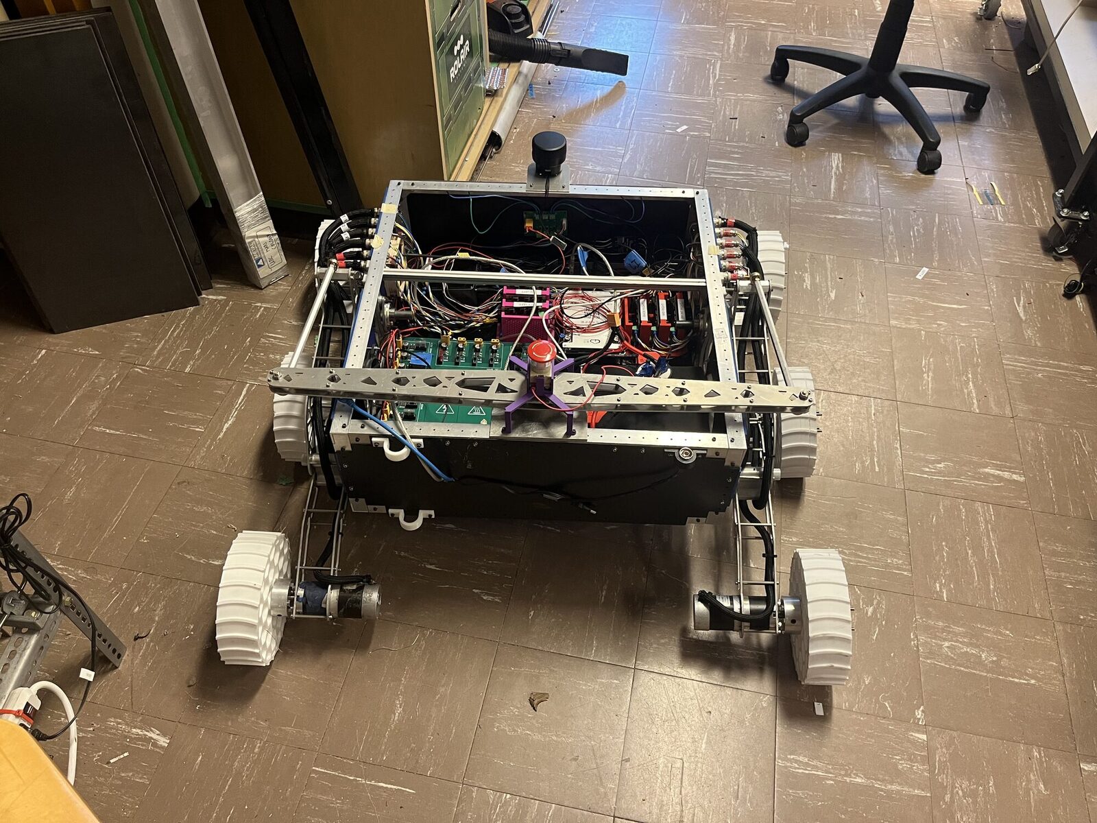
The frame is a modular foundation of the chassis. It allows for flexibility in attachment location, and is designed for easy assembly in the field. The frame allows the rover to be a test and competition vehicle.

The design philosophy was to make the frame as flexible as possible. To minimize assembly, the frame was bent to reduce the number of components, and the number of fasteners was minimized. PEM nuts are used for screwing attachments into the frame. Simply put, the frame is an electrical enclosure that is designed for modularity, flexibility, and reliability.

The frame has to survive thousands of cycles of assembly and disassembly, bumps while traversing over rough terrain, and unexpected weather, if need be. The frame allows for the rover to function as a device in a stable, predictable manner.

Tech Specs

Material
Powder-coated aluminium 5052-H12
Dimensions
600 × 590 × 200 mm
Weight
5 kg
Attachment points
400+
Weather resistance
Rain- and dust-proof
Wiring
Super clean
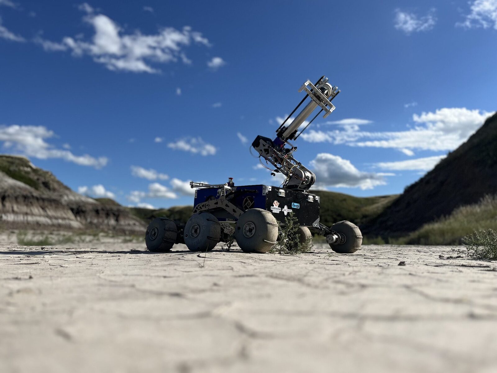
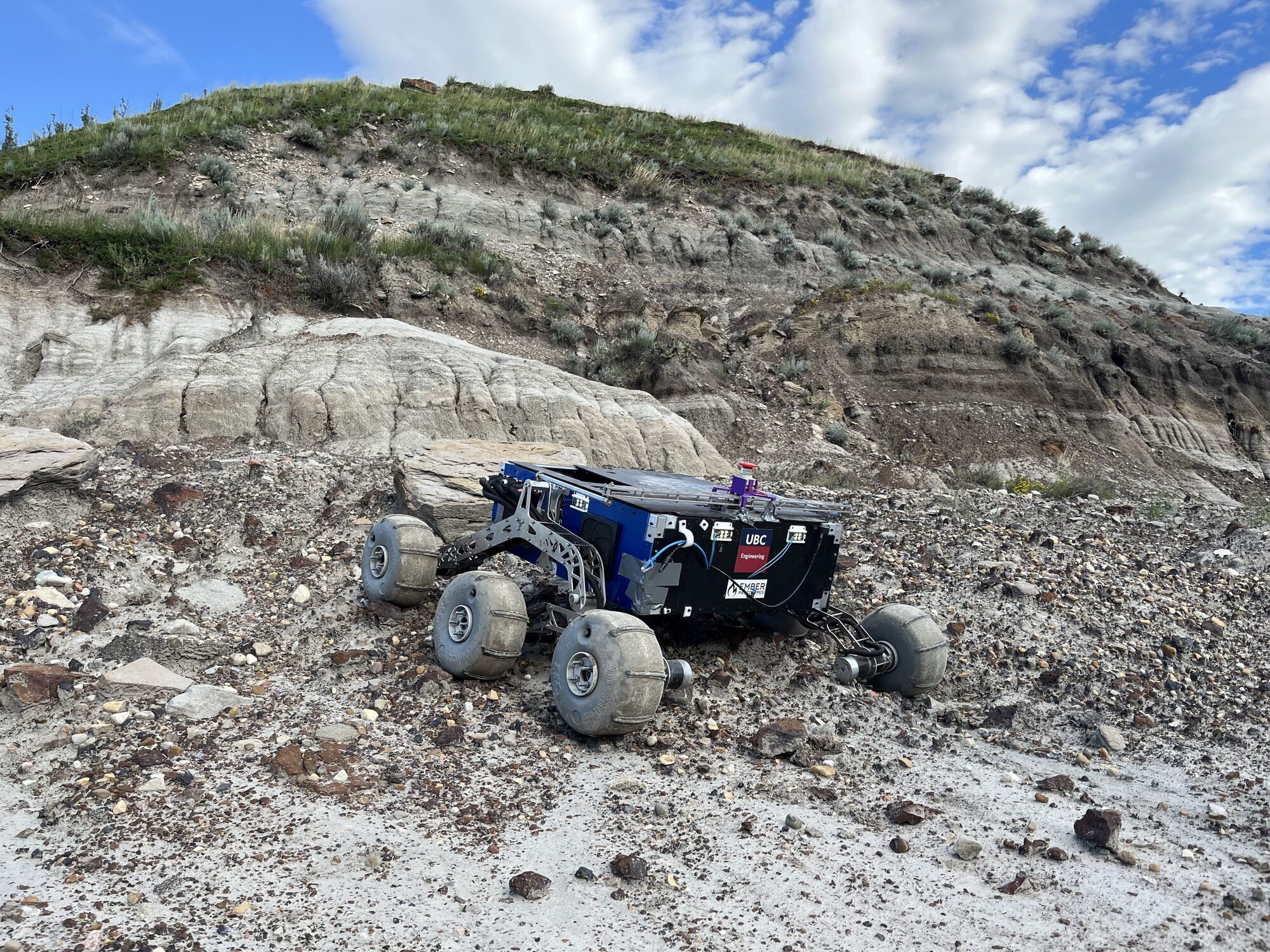
Six-wheel rocker-bogie in the Drumheller badlands.
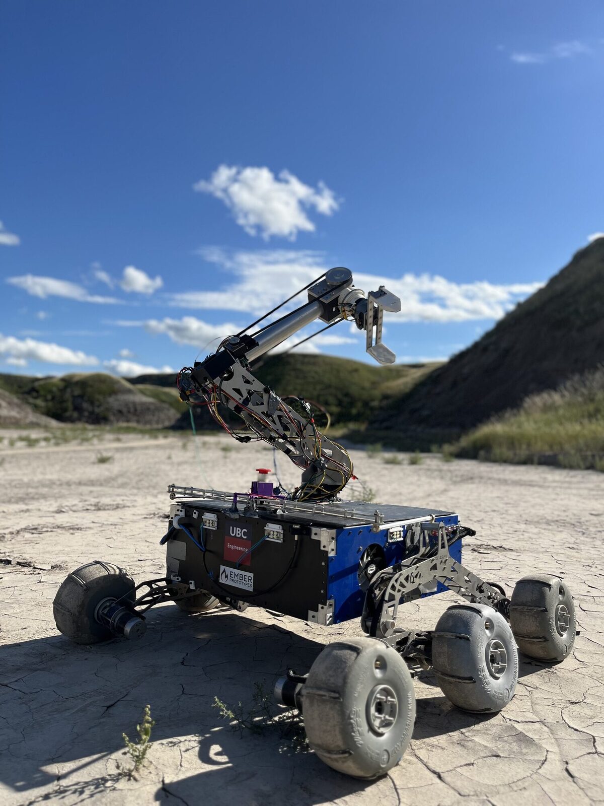
Rear three-quarter view.

1 / 4

Drivetrain

Allows traversal over challenging terrain while keeping the chassis level and maintaining traction.

The rocker-bogie suspension system allows for traversal over uneven terrain while still maintaining the vehicle more or less level with equal contact force on each wheel. Six wheels follow the tried-and-tested NASA design that has been used for three generations of rover.

The design philosophy of the rocker-bogie suspension system is weight minimization. Topology optimization was performed on the differential and the rocker-bogie legs. The rocker-bogie system has a greater moment of inertia due to the use of struts that increase the second moment of area while minimizing added weight, similar to a plane wing. Our drivetrain was selected to optimize available power per kg while maintaining speed and hill climbing ability.

Obstacles we need to traverse can be up to 30 cm in height, drops up to 1 m, and hills as steep as 35°. The suspension system must be able to endure forces that include the weight of the rover, arm, and any added components all while handling this rough terrain.

Tech Specs

Wheels
6
Mass
6 kg
Power
900 W
Torque
33 N·m
Max speed
13 km/h
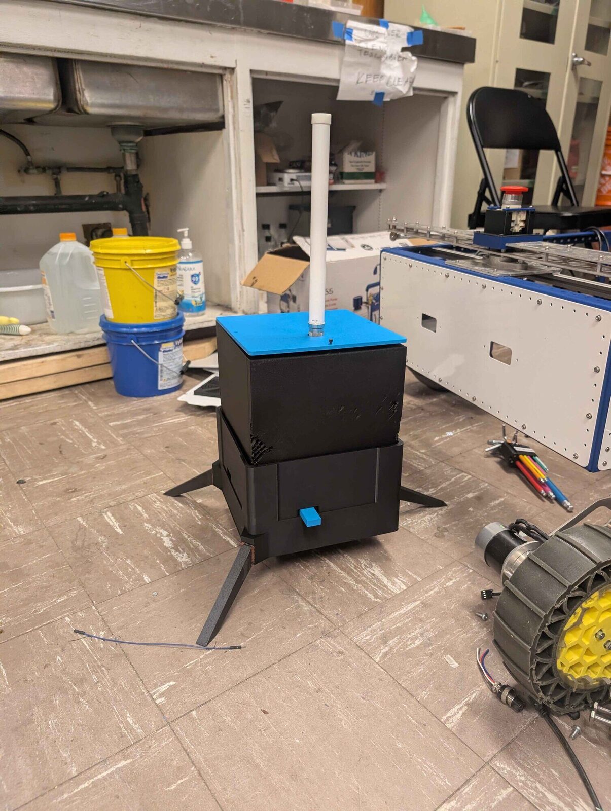
The assembled comms relay on its stand.

Comms Relay

Deployable module to increase the range of the rover.

The comms relay allows for the rover to communicate over longer distances or around structures that block the signal from the comms base antenna. The comms relay can deploy from the rover automatically, and allows for the absence of human intervention in extending the rover's range.

The comms relay is designed around deploying the most stable and reliable relay while still ensuring portability. Still in the developmental and testing phases, the comms relay relies on a rack and pinion mechanism that prioritizes reliability.

The comms relay has to survive the inclement weather, harsh terrain, and unpredictable landing conditions.

Tech Specs

Material
3D-printed PLA
Weight
2 kg
Deployable height
0.4 m